Please note, this document is for information only, different requirements apply for different manufacturers and types of equipment!
Main compliance criteria and requirements for the choice of installation site:
- Space requirements
- Building load capacity, statics
- Magnetic shielding
- Electromagnetic interference, vibration, interference
- System deliverability
- Electricity network
- Cooling
- Quench tube design, emergency suction
- Space requirements
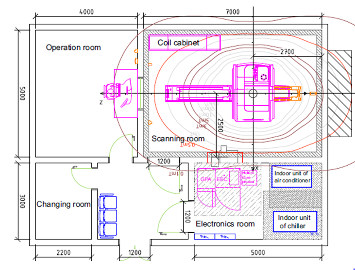
MR equipment rooms, their approximate proposed dimensions:
- Examination room: 5×7 m, minimum ceiling height 2,8 m
- Controller/Operator room: 5×4 m
- Technical room: 5×5 m, ceiling height: 2.8-3 metres
- Changing rooms, preparation, waiting: on request
- it is recommended to take into account the space requirements of accessories (sponges, rolls, blankets, paper towels, injector, etc.)
Typical placement schemes:
- Building load capacity, statics
It is not just the weight of the MR equipment that is important, the building must be able to accommodate the equipment, the electronics cabinets, the Faraday cage and any magnetic shielding that may be needed. Typical masses are:
- Magnet: 3500 – 4500 kg
- Magnet covers, cables, test table: 1500 kg
- MR electronics: 1000-3000 kg
- Faraday fish: 5000 kg
- Shielding: 3000 kg
- Total: 14000 – 17000 kg
In the test bench, a machine base must be constructed in an area of about 3×3 m under the magnet, which can support the weight of the equipment and withstand the vibrations caused by the gradient coils. The magnets usually have legs, the load bearing capacity of the four slab sections under the legs should be around 10-20kN.
The loads associated with the other equipment are located in and around the 30-40 m2 area of the test facility. The nearly 800 kg mass of shielding is usually installed under the magnet, the rest of the shielding under the Faraday cage, but occasionally, depending on the design, it may also cause additional loads on the adjacent room wall.
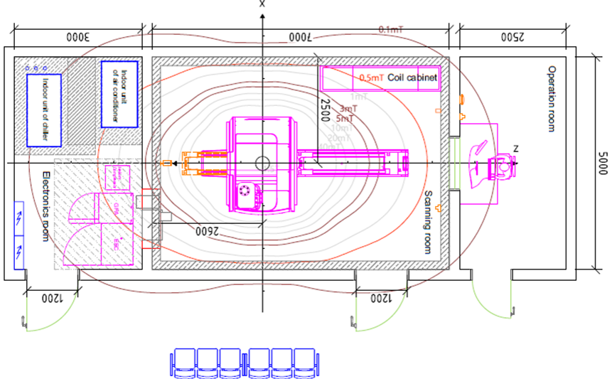
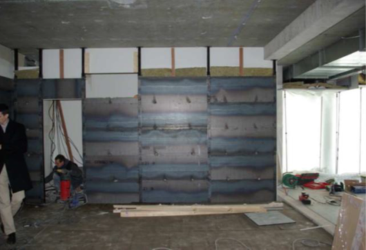
- Magnetic shielding
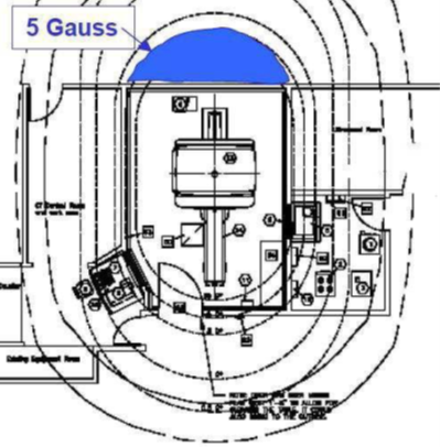
The magnetic field B0 is continuously present in the environment of the excited MR device, even when it is switched off or in the event of a power failure. This magnetic field also has an effect in the environment of the equipment. It is imperative that this effect does not affect the operation of equipment and devices installed in the surrounding premises, nor does it affect staff and passers-by. The relevant limit is 5 Gauss maximum.
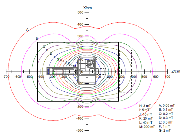
Magnetic shielding can reduce the strength of the magnetic field around the equipment:
- Electromagnetic interference, vibration, interference:
The MR environment may provide interference signals and effects that can affect the operation of the equipment. When choosing the location, it must be taken into account that these disturbance signals and effects (static, dynamic, vibration, AC) cannot be compensated for and excluded in many cases:
- roads, cars, lifts: approx. 10 metres
- tram, metro, underground, train: approx. 100 metres
- transformer station, high-voltage or high-power AC cable, any high-power motor-driven device: current-dependent, see Fig:
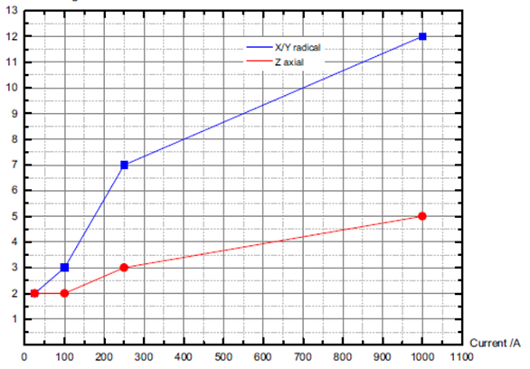
- water pipes, gas pipes : must not be routed directly above or below the tester.
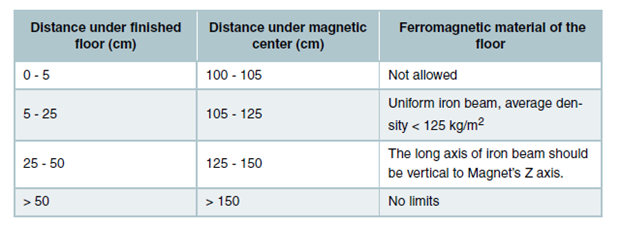
- storage of large quantities of ferromagnetic material: 10 metres
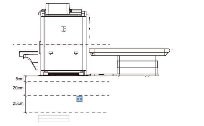
- the amount of iron directly under the equipment is also limited:
- System deliverability
Not only does the building need to retain the equipment, but it also needs to be able to arrange the delivery of the equipment prior to installation. There are many different ways of transporting the main units to their final location, taking into account the size and weight of the units to be delivered, the width and height of the delivery route and, of course, the load capacity. Care must be taken to ensure that differences in level are adequately bridged and that existing walkways are protected.
Even after the building modifications, there must be a supply route for the supply of components, units and materials necessary for servicing the MR equipment (gradient coil, helium cans, etc.)
- Electricity network
Electrical demand:
- Voltage and frequency: 380/400/415VAC +-10%, 50Hz
- Power: 50-80 kVA depending on the equipment
- Cooling power requirements: 40-70 kVA
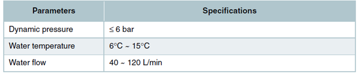
- Cooling
The function of the air handling system, the coolant production system, is to dissipate the heat generated by the equipment, to exchange the air in the rooms, to ensure a dust-free air space, and possibly to set the right humidity. The technological cooling of equipment is described in the table below:
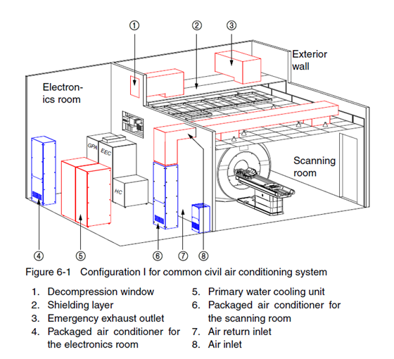
Example of air handling:
- Quench tube design, emergency suction
A cryogenic venting design (Quench tube) is used to vent large amounts of helium to the outside during possible magnet expansion in the tester. The diameter of the tube depends on the length of the tube and the number of elbow joints it contains, typically 20-40 cm in diameter.
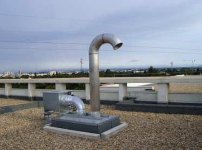
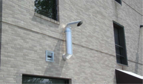
Part of the ventilation system is the emergency extraction in the test room: to extract the helium that escapes from the magnet during servicing and to ensure sufficient oxygen levels in the room.